OPC, OLED and some LEDs for Good Measure
If you've ever been to an industrial plant that makes anything that flies (Airplanes, Helicopters, Space Shuttles, etc.) they more than likely have some large Ovens, Presses or Autoclaves that are part of their production process. OLE for Process Control (OPC) is basically a set of standards / specifications for industrial telecommunications. If the equipment has the support built in to be an OPC Server, and you have support in your software for OPC to connect to the OPC Server, you can communicate in a common way to that equipment. Most often the transport medium is either a Serial connection or an Ethernet Connection. I work for a company that not only builds the Ovens, Presses and Autoclaves, but also creates the software that controls them (my job). Think of these as a typical oven and you are baking a cake. You mix up the recipe, preheat the oven and bake the cake for a set period of time and temperature. Now imagine if you didn't need to set the temperature or timer. Instead, the oven automatically used the recipe to control the oven to bake the cake until it was ready and then turned off the oven. It would require some temperature controlling abilities and some sensors to monitor how far along the cake is done and once done, it would quickly cool down the oven so it didn't continue to bake. This is similar to what any of these industrial devices do. But in some instances, you need to have not only temperature, but also pressure and vacuum.
Being that I have the good fortune of being able to work from home and these industrial devices are rather large (some of them you can put an entire wing of a plane into them), I needed some way to test without having to have connectivity to one of these devices. My company does have VPN, and I can connect to the office network and even connect to and control a 'real' device. However, that also requires someone on-site, monitoring the device, just for safety sake. I needed a better option for the early testing phase (then once I know the bugs are under control and things have stabilized, I can move on to a 'live' environment). Arduino to the rescue.
First off, the requirements:
1 - There are a bunch of system status bits (Equipment Ready, Run Active, Run Paused, Connectivity Monitor and Alarms (when something doesn't seem right) that I want to be able to monitor even when the screen of my computer is off ... some different colored LEDs would do the trick.
2 - I wanted also to be able to monitor some of the actual control and sensor values (Temperature In/Out, Pressure In/Out, Vacuum In/Out, etc). The Out data is the controlling part, it sets the value that the devices need to work on getting to (Heat/Cooling, Pressure +/- and/or Vacuum +/-). The In data is how to monitor how we're doing in reaching the goals of the Recipe. Again, I wouldn't mind seeing this when the screen to the computer was off... a small OLED Display module should do the trick.
3 - I wanted to communicate using OPC. Yes, I could just use a Serial or Ethernet connection, but then I'd have to write an Arduino driver for our software... but since we already support OPC, it would be nice not to have to write another driver ... if I could find an Arduino OPC library/server solution... and I did ... the OPC Server for Arduino by Software Tools for Makers.
And, basic component requirements:
- An Arduino Mega (an UNO barely has enough memory for the OLED Display module, let alone adding the OPC support) ... I have an official Mega and I have a clone from Keyestudio ... I'm using the Keyestudio for this project ... $11.99 at the time of this writing on Amazon.
- An OLE Display Module (from AdaFruit) ... $9.99 on Amazon.
- 5 different colored LEDs (and 330 Ohm resistors) ... Elfeland 375 LED (5-color, 2 size) set for $11.99 on Amazon ... I'll likely never need to buy LEDs again ... the resistors I used were also from a set of resistors I bought on Amazon (Elenco 365 resistor set) ... 5 resistors for each OHM ... so perfect # for 330 OHM resistors) ... at the time of this writing, they are $12.93 on Amazon.
- Some patch cables and a breadboard to hook everything up ... I had these already, but they aren't terribly expensive.
I won't bore you with connecting everything, there are plenty of tutorials for connecting LEDs to an Arduino and the OLE Display Module connection is as simple as it gets.
Now the software:
- We need the Adafruit SSD1306 library, which also requires the Adafruith GFX library from Adafruit for the OLED Display Module.
- We need the OPC library from Software Tools for Makers for OPC Support (get this from the Arduino Library Manager)
- I also use a Timer library by Simon Monk ... this allows me to read/write to the OPC Server and update the OLED at a set timed interval event (rather than having it occur every iteration of the loop() function ... or try to control it within the loop() function) ... just search for Timer for Arduino Simon Monk in Google ... The Arduino Playground link (for me it was the second in the list) ... but I think the first link(to Github) is where you'll end up getting it from ... but the Playground link shows you examples of it's use.
- Everything else is standard Arduino.
OPC 'Clients' use preset Tags defined in the OPC Server. So, for example, if I wanted to get (or set) the temperature of an oven ... I might have a Tag on the OPC Server called Temp and I would read (or write) based on the Tag to get (or set) the temperature values from an OPC Client.
The OPC Library allows me to setup those tags (including different data types for the values).
The actual OPC Server in this instance is a combination of the setup part (the tags) within the Arduino code and a windows application that you can register / de-register as needed that actually communicates to the Arduino from the PC through the standard OPC Enumeration process (for more info check out the OPC Foundation pages) and provides the OPC connectivity (the beauty of OPC is that a lot of manufactures of PLCs, DACUs, etc. do have support for OPC, so you don't need to worry about the details of communicating with those devices, all you need to do, is set up the Tags and run the OPC Server for the device and then communicate using the OPC standards from any Clients.
So, I setup all the tags I needed. I setup 2 Temperature Controls (read/write), a Pressure Control (read/write), a Vacuum Control (read/write). 8 Temperature Sensors for each Temperature Control (read only), 4 Vacuum Sensors (read only) and the 5 aforementioned system bits (read/write).
Some example Code...
Let's take a second and talk about Controls vs Sensors. Controls in my world are both readable and writeable ... for example: when I write a value for a temperature control, I'm asking the OPC connected device to Heat Up or Cool Down to a specific temperature. The read portion of the control not only monitors the device, but the OPC Client software we have also controls how far apart the write and read values can get without recognizing it as a possible problem (and throw an alarm if it is). Sensors are read-only, any number of sensors can be active in a device to monitor whatever is 'baking'. So, for example, back to the cake scenario, let's assume it's square. We might place a sensor an inch or so from each corner and then one right in the middle ... and we'd monitor those sensors not only for temperature, but we'd also compare for consistency (this may also determine how fast the control tells the device to heat up).
Moving on:
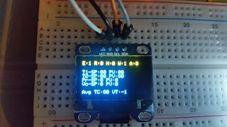
I wrote the code to display most everything on the OLED Display module. I used the top line (which is yellow) to show the system bits, then I displayed (blue) the Temperature(s) In/Out, the Pressure In/Out and the Vacuum In/Out ... I also added a line for Avg Temp1 and Avg Vacuum sensor values (a little short on room for the Temp2 values, but I can see those if needed on the computer screen). I might add a toggle button someday so I can have a second view of data on the OLED, where when I push the button it would toggle between a couple different screens, but that's a future project. Update: I actually did exactly as described. I added a button and when pressed it changes back and forth between 2 different pages of information ... dependent on the page #, the OLED displays only that page's info. I left the System Bits at the top on both pages.
A sample of what's being sent to the OLED. The yellow are the status bits, the blue are the details (note: SP = Out, PV = In, TCs are temperature sensors, VTs are vacuum sensors). The Equipment is ready (E:1), We're not running anything (R:0), We are not Pause (H:0 - H = Hold), the connection monitor (that goes on and off every 5 seconds) is current on (W:1 - W = WatchDog), there are no alarms (A:0). The Temperatures (T1 and T2) are idle and 80 degrees (not real temperatures, just default value set by our software) and the sensors are keeping up at 80 degrees. The Pressure and Vacuum are at 0. Avg Temperature Sensors values are at 80 degrees, the Avg Vacuum Sensor values are at -1. Update: The Avg Sensor values are now on Page 2 of the OLED Display and accessed by a pushbutton connected to the Arduino. Also the Avg Vacuum Sensor value now shows 0 when idle... there was a bug ... discussed later.
I then added the code to turn on/off the LEDs dependent on the system bits (yes, they are duplicated by the OLED display, but it's nice to be able to look into my home office and see what's currently happening during a test (which is pretty much impossible at a distance with the OLED). This is typical Arduino LED handling.
The final step was to add code so that the input of the controls and sensors basically followed the controls (to simulate a running device). There may be a slight bug or initialization error in the Avg Vacuum values (VT) ... it shows -1 on the OLED Display monitor ... it probably should be 0 ... it doesn't really matter, but it's something to look at in the future. Update: yes it was a bug, it now shows 0 as it should when idle ... it was actually a divide-by-zero error... interesting that it returned a -1.
A photo of the whole unit ... equipment status is on ... everything else is currently off (although the connectivity bit will come back on in < 5 seconds). There are 5 LEDs although it's a bit hard to tell. Blue - Alarm Notification, White - Connectivity On/Off every 5 seconds (controlled with our software), Green - Running a Recipe, Red - Run is Paused and Yellow - Equipment Ready). Update: There is now a Button on the right side of the breadboard with a 10K OHM resistor and the appropriate patch cables ... a press of the button now toggles the OLED display back and forth between two pages of information.

This ended up being a pretty fun (and a useful real-world) project.
A couple notes:
You have to close and de-register the OPC Server for Arduino if you are using the Serial support to upload a new/updated program to the Arduino ... then re-register when you are ready to run ... just keep that in mind. If you use the Ethernet support (also available with the OPC Server for Arduino), that shouldn't be an issue.
The OLED Display module should be connected to 3.3V (although connecting to 5V seems to work too).
Typically you can query the OPC Server for a list of available Tags. I have been unable to get this to work with the OPC Server for Arduino although that might be due to the fact that (at least the Serial mode) doesn't allow multiple connections (from different users). Our software uses two connections, one for typical execution (our service user), one for configuration (the currently logged in user)). This works on every other OPC Server I've seen (including those using Serial communication for transport).
Latest Update: I had added an active buzzer to the mix so that when an Alarm occurs, there's some noise along with the Blue LED illuminating. This is nice for when I'm doing something else while running a test and not paying too much attention to the the actual run (since I typically don't care until the cure finishes and I can see the results). I also moved everything from the large breadboard to a prototype shield that has a small breadboard. It was tight, but do-able. I also changed most values (and calculations) from int to float ... I am going to eventually add some randomness to the results (so that TC (Temperature Thermocouple sensors) and VT (Vacuum Transducer sensor) simulation is a bit more realistic). I figure I'll create an array or random values between -5 and 5, divided by 100 and increment the TC and VT values by those values every time I'm calculating the new values for sensors. I may divide by a larger number and let rounding handle the rest too ... haven't decided yet. Update: I actually did the random update ... it basically only goes between 0 and 3, I divide by 1000 and I increase or decrease input values by the amount depending on the direction the next value needs to go. This works out to be a pretty dynamic and random (but not too random of a way) to have a little variability of the sensor inputs. I also changed the OPC timer to update 3 times a second rather than once a second. So the absolute largest difference you will see within a second is += .009 degrees (or temperature or hg (of vacuum) ... so it could round to .01 (or not) dependent on the random values used.
Being that I have the good fortune of being able to work from home and these industrial devices are rather large (some of them you can put an entire wing of a plane into them), I needed some way to test without having to have connectivity to one of these devices. My company does have VPN, and I can connect to the office network and even connect to and control a 'real' device. However, that also requires someone on-site, monitoring the device, just for safety sake. I needed a better option for the early testing phase (then once I know the bugs are under control and things have stabilized, I can move on to a 'live' environment). Arduino to the rescue.
First off, the requirements:
1 - There are a bunch of system status bits (Equipment Ready, Run Active, Run Paused, Connectivity Monitor and Alarms (when something doesn't seem right) that I want to be able to monitor even when the screen of my computer is off ... some different colored LEDs would do the trick.
2 - I wanted also to be able to monitor some of the actual control and sensor values (Temperature In/Out, Pressure In/Out, Vacuum In/Out, etc). The Out data is the controlling part, it sets the value that the devices need to work on getting to (Heat/Cooling, Pressure +/- and/or Vacuum +/-). The In data is how to monitor how we're doing in reaching the goals of the Recipe. Again, I wouldn't mind seeing this when the screen to the computer was off... a small OLED Display module should do the trick.
3 - I wanted to communicate using OPC. Yes, I could just use a Serial or Ethernet connection, but then I'd have to write an Arduino driver for our software... but since we already support OPC, it would be nice not to have to write another driver ... if I could find an Arduino OPC library/server solution... and I did ... the OPC Server for Arduino by Software Tools for Makers.
And, basic component requirements:
- An Arduino Mega (an UNO barely has enough memory for the OLED Display module, let alone adding the OPC support) ... I have an official Mega and I have a clone from Keyestudio ... I'm using the Keyestudio for this project ... $11.99 at the time of this writing on Amazon.
- An OLE Display Module (from AdaFruit) ... $9.99 on Amazon.
- 5 different colored LEDs (and 330 Ohm resistors) ... Elfeland 375 LED (5-color, 2 size) set for $11.99 on Amazon ... I'll likely never need to buy LEDs again ... the resistors I used were also from a set of resistors I bought on Amazon (Elenco 365 resistor set) ... 5 resistors for each OHM ... so perfect # for 330 OHM resistors) ... at the time of this writing, they are $12.93 on Amazon.
- Some patch cables and a breadboard to hook everything up ... I had these already, but they aren't terribly expensive.
I won't bore you with connecting everything, there are plenty of tutorials for connecting LEDs to an Arduino and the OLE Display Module connection is as simple as it gets.
Now the software:
- We need the Adafruit SSD1306 library, which also requires the Adafruith GFX library from Adafruit for the OLED Display Module.
- We need the OPC library from Software Tools for Makers for OPC Support (get this from the Arduino Library Manager)
- I also use a Timer library by Simon Monk ... this allows me to read/write to the OPC Server and update the OLED at a set timed interval event (rather than having it occur every iteration of the loop() function ... or try to control it within the loop() function) ... just search for Timer for Arduino Simon Monk in Google ... The Arduino Playground link (for me it was the second in the list) ... but I think the first link(to Github) is where you'll end up getting it from ... but the Playground link shows you examples of it's use.
- Everything else is standard Arduino.
OPC 'Clients' use preset Tags defined in the OPC Server. So, for example, if I wanted to get (or set) the temperature of an oven ... I might have a Tag on the OPC Server called Temp and I would read (or write) based on the Tag to get (or set) the temperature values from an OPC Client.
The OPC Library allows me to setup those tags (including different data types for the values).
The actual OPC Server in this instance is a combination of the setup part (the tags) within the Arduino code and a windows application that you can register / de-register as needed that actually communicates to the Arduino from the PC through the standard OPC Enumeration process (for more info check out the OPC Foundation pages) and provides the OPC connectivity (the beauty of OPC is that a lot of manufactures of PLCs, DACUs, etc. do have support for OPC, so you don't need to worry about the details of communicating with those devices, all you need to do, is set up the Tags and run the OPC Server for the device and then communicate using the OPC standards from any Clients.
So, I setup all the tags I needed. I setup 2 Temperature Controls (read/write), a Pressure Control (read/write), a Vacuum Control (read/write). 8 Temperature Sensors for each Temperature Control (read only), 4 Vacuum Sensors (read only) and the 5 aforementioned system bits (read/write).
Some example Code...
// Initialize The OPC Serial Object
OPCSerial aOPCSerial;

.
.
.

// Then in the setup() function ...

 aOPCSerial.setup(); // Setup the OPC Serial device.

  // Add some tags that we want to use from our OPC compatible software.
  // Temperature Control 'write'
  aOPCSerial.addItem("TSP",opc_readwrite, opc_int, item_int_tempsp);
  // Temperature Control 'read'
  aOPCSerial.addItem("TPV",opc_read, opc_int, item_int_temppv);
  // The 8 Temperature Sensors
  aOPCSerial.addItem("TC1",opc_read, opc_int, item_int_tc);
  aOPCSerial.addItem("TC2",opc_read, opc_int, item_int_tc);
  aOPCSerial.addItem("TC3",opc_read, opc_int, item_int_tc);
  aOPCSerial.addItem("TC4",opc_read, opc_int, item_int_tc);
  aOPCSerial.addItem("TC5",opc_read, opc_int, item_int_tc);
  aOPCSerial.addItem("TC6",opc_read, opc_int, item_int_tc);
  aOPCSerial.addItem("TC7",opc_read, opc_int, item_int_tc);
  aOPCSerial.addItem("TC8",opc_read, opc_int, item_int_tc);
  .
  .
  .
  etc.  // other controls / sensors / system bits / etc.

  // The Temperature Control callbacks for the OPC Server  ...

// Save the value that was sent to us from the OPC 'Client'
int item_int_tempsp(const char *itemID, const opcOperation opcOP, const int value)
{
  if (opcOP == opc_write)
    TempSP = value;

  return TempSP;
}

// Return the value that was requested from the OPC 'Client'
int item_int_temppv(const char *itemID, const opcOperation opcOP, const int value)
{
  return TempPV;
}

// The sensor callback ... I store the items in an integer array, so I figure out the array index
// based on the tag number and return the value.
int item_int_tc(const char *itemID, const opcOperation opcOP, const int value)
{
  int tcnum = atoi(&itemID[2]) - 1;
  return TC[tcnum];
}
Let's take a second and talk about Controls vs Sensors. Controls in my world are both readable and writeable ... for example: when I write a value for a temperature control, I'm asking the OPC connected device to Heat Up or Cool Down to a specific temperature. The read portion of the control not only monitors the device, but the OPC Client software we have also controls how far apart the write and read values can get without recognizing it as a possible problem (and throw an alarm if it is). Sensors are read-only, any number of sensors can be active in a device to monitor whatever is 'baking'. So, for example, back to the cake scenario, let's assume it's square. We might place a sensor an inch or so from each corner and then one right in the middle ... and we'd monitor those sensors not only for temperature, but we'd also compare for consistency (this may also determine how fast the control tells the device to heat up).
Moving on:
I wrote the code to display most everything on the OLED Display module. I used the top line (which is yellow) to show the system bits, then I displayed (blue) the Temperature(s) In/Out, the Pressure In/Out and the Vacuum In/Out ... I also added a line for Avg Temp1 and Avg Vacuum sensor values (a little short on room for the Temp2 values, but I can see those if needed on the computer screen). I might add a toggle button someday so I can have a second view of data on the OLED, where when I push the button it would toggle between a couple different screens, but that's a future project. Update: I actually did exactly as described. I added a button and when pressed it changes back and forth between 2 different pages of information ... dependent on the page #, the OLED displays only that page's info. I left the System Bits at the top on both pages.
A sample of what's being sent to the OLED. The yellow are the status bits, the blue are the details (note: SP = Out, PV = In, TCs are temperature sensors, VTs are vacuum sensors). The Equipment is ready (E:1), We're not running anything (R:0), We are not Pause (H:0 - H = Hold), the connection monitor (that goes on and off every 5 seconds) is current on (W:1 - W = WatchDog), there are no alarms (A:0). The Temperatures (T1 and T2) are idle and 80 degrees (not real temperatures, just default value set by our software) and the sensors are keeping up at 80 degrees. The Pressure and Vacuum are at 0. Avg Temperature Sensors values are at 80 degrees, the Avg Vacuum Sensor values are at -1. Update: The Avg Sensor values are now on Page 2 of the OLED Display and accessed by a pushbutton connected to the Arduino. Also the Avg Vacuum Sensor value now shows 0 when idle... there was a bug ... discussed later.

// Initialize the OLED display object
#define OLED_RESET 4
Adafruit_SSD1306 display(OLED_RESET);
.
.
.
Then in the setup() function ...

// Begin the OLED display device (using the correct i2c address of 0x3C)
// Note: There is an i2cScanner program that will tell you this address, it may be
//           useful to download and run this to make sure you know the correct address.
display.begin(SSD1306_SWITCHCAPVCC, 0x3C);

// Clear the buffer.
  display.clearDisplay();

  // Show the System Bits
  // Arguably the most important part of this is that you use print if you
  // don't go to the next line and you use println if you do.
  display.setTextSize(1);
  display.setTextColor(WHITE);
  display.setCursor(0,0);
  display.print("E:");
  display.print(EquipmentStatus);
  display.print(" R:");
  display.print(RunStatus);
  display.print(" H:");
  display.print(HoldStatus);
  display.print(" W:");
  display.print(WatchDog);
  display.print(" A:");
  display.println(ProcessAlarm);
  display.println(""); // Blank Line

  // Show the rest of the code (Controls)
 display.print("T1-SP:");
 display.print((InTransition) ? TransTempSP : TempSP);
 display.print(" PV:");
 display.println((InTransition) ? TransTempSP : TempPV);
 display.print("T2-SP:");
 display.print((InTransition) ? TransTemp2SP : Temp2SP);
 display.print(" PV:");
 display.println((InTransition) ? TransTemp2PV : Temp2PV);
 display.print("Pr-SP:");
 display.print((InTransition) ? TransPressSP : PressSP);
 display.print(" PV:");
 display.println((InTransition) ? TransPressSP : PressPV);
 display.print("Vc-SP:");
 display.print((InTransition) ? TransVacSP : VacSP);
 display.print(" PV:");
 display.println((InTransition) ? TransVacPV : VacPV);
 .
 .
 .
 etc.

// and finally ... don't forget this or it won't display on the OLED!!!
  display.display();
I then added the code to turn on/off the LEDs dependent on the system bits (yes, they are duplicated by the OLED display, but it's nice to be able to look into my home office and see what's currently happening during a test (which is pretty much impossible at a distance with the OLED). This is typical Arduino LED handling.
The final step was to add code so that the input of the controls and sensors basically followed the controls (to simulate a running device). There may be a slight bug or initialization error in the Avg Vacuum values (VT) ... it shows -1 on the OLED Display monitor ... it probably should be 0 ... it doesn't really matter, but it's something to look at in the future. Update: yes it was a bug, it now shows 0 as it should when idle ... it was actually a divide-by-zero error... interesting that it returned a -1.
// The simulation just follows the value written to the Temperature Control (so it increases or
// decreases both the control read and all of the Temperature Sensors ... by a predefined incremental
// amount every time the timer updates ... so the speed at which the device heats up or cools down is
// controlled by both how often the timer updates AND the increment value).

void updateTemp()
{
  // Temperature Handling
  if (TempSP != TempPV)
  {
    if (TempInc > 0 && TempPV > TempSP)
    {
      TempInc = -1 * TempIncVal;
    }
    else if (TempInc < 0 && TempPV < TempSP)
    {
      TempInc = TempIncVal;
    }

    TempPV += TempInc;

    for (int i = 0; i < 8; i++)
    {
        TC[i] += TempInc;
    }
  }
}
A photo of the whole unit ... equipment status is on ... everything else is currently off (although the connectivity bit will come back on in < 5 seconds). There are 5 LEDs although it's a bit hard to tell. Blue - Alarm Notification, White - Connectivity On/Off every 5 seconds (controlled with our software), Green - Running a Recipe, Red - Run is Paused and Yellow - Equipment Ready). Update: There is now a Button on the right side of the breadboard with a 10K OHM resistor and the appropriate patch cables ... a press of the button now toggles the OLED display back and forth between two pages of information.

This ended up being a pretty fun (and a useful real-world) project.
A couple notes:
You have to close and de-register the OPC Server for Arduino if you are using the Serial support to upload a new/updated program to the Arduino ... then re-register when you are ready to run ... just keep that in mind. If you use the Ethernet support (also available with the OPC Server for Arduino), that shouldn't be an issue.
The OLED Display module should be connected to 3.3V (although connecting to 5V seems to work too).
Typically you can query the OPC Server for a list of available Tags. I have been unable to get this to work with the OPC Server for Arduino although that might be due to the fact that (at least the Serial mode) doesn't allow multiple connections (from different users). Our software uses two connections, one for typical execution (our service user), one for configuration (the currently logged in user)). This works on every other OPC Server I've seen (including those using Serial communication for transport).
Latest Update: I had added an active buzzer to the mix so that when an Alarm occurs, there's some noise along with the Blue LED illuminating. This is nice for when I'm doing something else while running a test and not paying too much attention to the the actual run (since I typically don't care until the cure finishes and I can see the results). I also moved everything from the large breadboard to a prototype shield that has a small breadboard. It was tight, but do-able. I also changed most values (and calculations) from int to float ... I am going to eventually add some randomness to the results (so that TC (Temperature Thermocouple sensors) and VT (Vacuum Transducer sensor) simulation is a bit more realistic). I figure I'll create an array or random values between -5 and 5, divided by 100 and increment the TC and VT values by those values every time I'm calculating the new values for sensors. I may divide by a larger number and let rounding handle the rest too ... haven't decided yet. Update: I actually did the random update ... it basically only goes between 0 and 3, I divide by 1000 and I increase or decrease input values by the amount depending on the direction the next value needs to go. This works out to be a pretty dynamic and random (but not too random of a way) to have a little variability of the sensor inputs. I also changed the OPC timer to update 3 times a second rather than once a second. So the absolute largest difference you will see within a second is += .009 degrees (or temperature or hg (of vacuum) ... so it could round to .01 (or not) dependent on the random values used.
Comments
Post a Comment